Usually, sheet metal parts are designed in their folded state, and with the click of a button, the flattened profiles can be extracted to create 2D drawings or to be sent directly to a laser cutter for profiling. There are three main approaches to creating a sheet metal part which are:
• Using sheet metal features such as base flanges, edges flanges and mitre flanges.
• Inserting bends into an existing, thin walled, part.
• Converting to sheet metal, which allows a sheet metal wrapper to be created around the faces of a non-sheet metal body.
Each method has its own benefits, but by far the most flexible is starting with a base flange and adding features to it. So let’s start by taking a look at this method.
Turning on the SolidWorks Sheet Metal Tab
Before getting started, to access the sheet metal features, the sheet metal tab will need to be enabled. If this isn’t visible, right click on any tab from the command manager whilst within a part file and choose Sheet Metal from the tabs menu. The sheet metal tab will then appear.
Base Flange Method
The base flange method starts by creating a 2D sketch. This sketch can either be enclosed, such as a rectangle, or open such as a single line, or channel shape. Whether the sketch is open or not will determine how the base flange feature is created.
When a base flange is created from an enclosed sketch, the sheet metal thickness is created perpendicular to the sketch plane, with the end result being a piece of sheet metal which has no bends.
When a base flange is created from an open sketch, such as this channel shape, the sheet metal thickness is offset about the sketch. Bends are automatically added within the base flange feature, so no fillets are needed within the sketch. Using the open sketch approach often allows a greater amount of information to be captured within the sketch, and can make it quicker to create a sheet metal part and easier to update later on.
It’s a good idea to think about your design intent and the driving information you have before deciding on which method is the best to use.
Insert Bends Method
Unlike the base flange method, insert bends requires solid, thin walled, geometry to already exist that can have bends added to it which in turn creates the sheet metal part. This method can be useful when the final shape is complex and/or includes angled flanges that create a mitred corner.
To turn a solid shape into a sheet metal part using insert bends, it firstly needs to be shelled, which gives a constant wall thickness, then the insert bends tool can be used.
The first selection defines the fixed face of the sheet metal part, when flattening the shape, this is the face that will stay still, and the other faces will unfold around it. Rips also need to be selected. Rips are the edges that will create a gap between any two adjacent flanges. When selecting an edge to rip, the change direction button can be toggled for each selection, and this defines whether the corners will be butted, indicated by the two way arrow, or lapped in either direction.
Convert to Sheet Metal Method
Convert to Sheet Metal is similar to Insert Bends in the fact that it requires existing geometry as an input, however this geometry does not have to be thin walled as the sheet metal thickness is defined within the convert to sheet metal feature.
The starting point for convert to sheet metal is a solid body, usually this would be modelled in SolidWorks, but you could also use an imported part.
Like with insert bends, one face needs to be selected as the main base flange but then any edge selected becomes a bend from which a new flange will be added.
Sheet Metal Properties
Each of the methods mentioned have a number of properties available when they are created, and these include options such as sheet thickness, bend radius, bend allowance and relief.
Sheet thickness
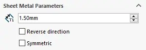
The thickness of the sheet metal that is to be created.
Bend radius

The internal radius that is created when a bend or flange is added. The external radius of a bend will equal this value, plus the sheet thickness.
Bend allowance
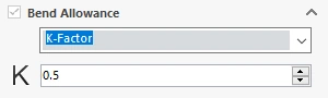
Either a value or calculation that is used to determine the length of the flattened sheet metal part. This value will change depending on bend angle, bend radius, material and sheet thickness. Sheet metal manufacturers should know these values, but for engineers designing sheet metal parts, be careful when supplying flattened parts for profiling and laser cutting as an inaccurate value here will result in an incorrect part.
Relief
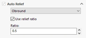
Controls how the corner where two flanges meet is treated, this can be set to tear, obround, or rectangular.
Secondary Features
Depending on the complexity of the part, additional features may need to be added to the sheet metal component, and this can include flanges, hems, jogs, and a variety of other features.
Secondary features inherit the properties that have been set within the initial sheet metal feature, so for example, the sheet thickness of a flange will always be the same as that of the main feature. Some properties can be overridden though, such as changing the bend radius for a specific bend when a new flange is added.
Flatten
At any point during the design process, the flattened version of a sheet metal part can be shown and this is done by clicking the flatten button. SOLIDWORKS sheet metal will only allow features to be created that can be flattened, so if features are added that can’t be flattened, errors will appear in the feature manager.
The flattened version can be easily added and detailed within a 2D drawing, from the views palette on the right hand side.