SolidWorks Weldments are a feature within the SolidWorks CAD software that facilitates the design and modelling of welded structures and frames. Ideal for industries such as construction, metalworking, and machinery, Weldments simplifies the creation of structural frameworks by offering an extensive library of standard profiles and the flexibility to create custom profiles when needed. Sketch-based design, automated trimming and mitering, end treatments, and assembly tools make it easy to create complex welded assemblies with precision. SolidWorks Weldments also automates the generation of cut lists and Bills of Materials (BOMs), simplifies the integration with structural analysis, and supports detailed documentation and drawing creation, making it an essential tool for engineers and designers involved in welded structure projects.
3D Sketches
In SolidWorks, 3D sketches are a powerful feature that allows you to create sketch geometry in three-dimensional space. While traditional 2D sketches are drawn on a single plane, 3D sketches can include lines, splines, arcs, and other sketch entities in three dimensions. Whilst they are particularly useful for creating complex or freeform shapes and can be applied to a variety of design scenarios, and are a great way to capture sketch geometry when working with weldments.
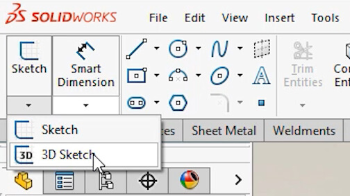
A 3D sketch is started from the drop-down underneath the standard sketch icon or the 3D sketch icon on the weldment tab. With a 3D sketch, there is no longer a reference to horizontal and vertical but instead the concept of, along X, Y and Z. To change the direction in which you are sketching when in a 3D sketch, hit the tab key to toggle between XY, YZ and ZX.
The best approach is often a mixture of 2D and 3D sketches. Double clicking an existing plane or creating a 3D sketch plane whilst in a 3D sketch can help you constrain along a particular axis. Focusing a sketch onto a specific plane when in a 3D sketch is done by double clicking it, and then double clicking into empty space to remove the focus.
Not only is it fast to capture sketch geometry using a 3D sketch, but because all of the dimensions are captured within a single sketch, it’s a fast way to be able to make adjustments too.
Structural Member Groups
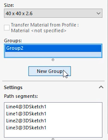
When adding structural members to a design, they are organized in groups. Within any single group, selections can be either parallel to each other, or they can form a chain. So for example, if a structural member needs to run around four sides of a frame, this can be done within a single group. If another member needs to be added, a new group is required and can be added within the properties on the left.
Locate Profile
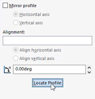
Once a selection has been made for a group, all of the options below are then specific to that group. A common thing to change is the location of the weldment profile relative to the selected sketch lines, and this is done using the locate profile button. This is useful as often you may need to toggle between internal, external or centered positioning. Additional anchor locations can be added by editing the base sketch of the weldment profile and adding in sketch points.
Corner Treatment
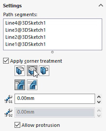
Within a structural member feature, corner treatment can be controlled wherever two or more members meet. This is adjusted within the properties on the left by toggling mitre, or butt joints, and can also be controlled per corner by clicking on the selection ball and modifying it’s properties. Changing the order of the trim determines the final cuts and can give you some impressive results like a 3-way mitre.
Trim/Extend
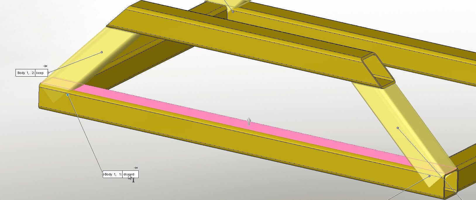
When a number of different structural members have been added to a design, it can create a scenario where individual members need to be cut back or lengthened. This can be done using the trim/extend tool. Rather than having to manually cut away at structural members, the trim/extend tool intelligently recognises the weldment bodies and allows you to choose how the members should be trimmed and will adjust existing members lengths accordingly.
Bounding Boxes
Structural members generate a lot of useful properties that can be referenced and displayed throughout SolidWorks. These are especially useful when shown in a 2D drawing cut-list table.
Solid bodies modelled within a weldment file, typically things like gussets, end pieces and irregular shaped supports, can also take properties with them too - providing a bounding box is created.
A bounding box in SolidWorks weldments is a 3D sketch that represents the smallest box in which the weldment can fit. It is created based on the X-Y plane, by default, and is based on the orientation of the weldment.
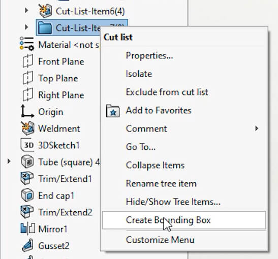
To create a bounding box, right-click on a cut list item in the Feature Manager Design Tree and select ‘create bounding box’
When the properties of that cut-list item are then shown, there are now additional properties that can be carried through into the 2D drawing.
2D Drawings
Because weldments create multi-body part files rather than assemblies, producing individual part drawings is slightly different to when working with assembled parts. Because of this, there are some specific tools used for presenting drawing views of weldment files.
Select Bodies
When you place a drawing view of a weldment you may only want to see a single body, or a selection of bodies, this can be achieved with the select bodies button on the properties in the top left. After clicking this, you will be taken to the 3d view where you can select the bodies you want to appear in the drawing view and any subsequent projected or child views.
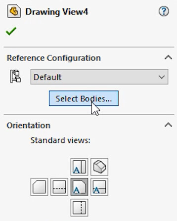
Relative View
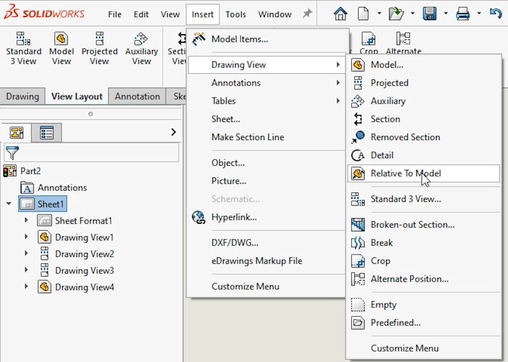
There will be scenarios where as well as selecting the bodies to show, you also want to manipulate the view to orient it differently within the 2D - this is where relative View helps.
Relative view allows you to pick a body or bodies to show in a view, but also allows the reorientation of either the front, top or right of that view too. This is great for weldment bodies that may have been modeled across an angle.
Other Uses
Often people think that weldments are only useful for welded frames, but don’t let the name mislead you. The weldment and structural member tools are useful for anything that comes in length. This could be furniture, timber framing, plastics or other types of metalwork.
Check out our ‘Furniture Design tips for SolidWorks’ video for more information.